ETD is building the future.
The NASA Goddard Engineering and Technology Directorate (ETD)
Where engineering and science partner to build the systems of tomorrow, today.
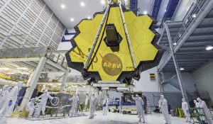
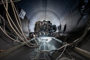
Photo: James Webb Space Telescope (JWST) – Looking back 13.5 billion years and searching for life beyond our solar system.
Building what has never been built before,
to discover the unknown.
At Goddard, the ETD supports missions, builds satellites and instruments, operates and controls spacecrafts and acquires and distributes data to the world-wide science community. The ETD’s data products are used to conduct research in Earth and space sciences that benefit the nation and the world.
Expanding Engineering Boundaries
Expanding today’s engineering boundaries through the application of emerging technologies to develop high-performance, cost-effective solutions to the most challenging problems.
End-to-end Science Mission Operation
The Engineering & Technology Directorate designs missions, builds satellites, develops instruments, and operates spacecrafts, in addition to acquiring and distributing scientific data globally.
Multidisciplinary Engineering Expertise
Provides multidisciplinary engineering expertise for the development of cutting-edge science and exploration systems and technologies.
Rich Working Environment
Wide ranging projects, multi-disciplinary problem solving, extensive laboratories and facilities and a college campus-like environment provide our employees with a rich work life.
Supporting the Goddard Mission
NASA Goddard Space Flight Center’s Greenbelt campus is home to the nation’s largest organization of scientists, engineers and technologists who conceive, design and build new technology to study the solar system and universe.
- The center employs 8,200 people and spans 1,270 acres.
- Goddard consists of six distinctive campuses and facilities across six states.
- The largest organization at Goddard is the Engineering and Technology Directorate. It is home to approximately 1,300 civil servants and 2,500 contractors who provide multidisciplinary engineering expertise to critical NASA missions.
- The ETD’s areas of expertise include advanced technology, hands-on experience for successfully executing space science missions, and a world-class systems engineering approach.
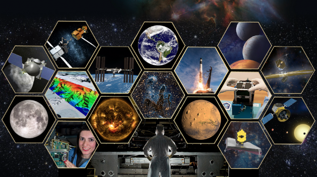
Our Work
The Engineering and Technology Directorate (ETD) is the engine that powers Goddard. ETD provides multi-disciplinary engineering expertise for the development of cutting-edge science and exploration systems and technologies in the following areas: Earth Science, Astrophysics, Solar System, Heliophysics and Exploration. In addition, ETD acquires and distributes science data worldwide.
ETD Updates
Explore featured stories, engineering news and information from leadership teams, the ETD’s work, education programs and outreach.
ETD Podcast
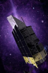
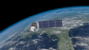
The Nancy Grace Roman Space Telescope
Join the Engineering and Technology Directorate as we interview Mark Melton, mission system engineer for the development of the Nancy Grace Roman Space Telescope. In this extended tell-all episode, learn more about the inner workings of the telescope, some interesting stories about its development and the significance of the project.
LISTEN | 11:19
Goddard is recognized as one of the top employers in the Federal Government.
NASA Goddard Space Flight Center’s Greenbelt campus is home to the nation’s largest organization of scientists, engineers, and technologists who build new technology to study the Earth, our solar system, and the universe.